| .. | ||
| boot | ||
| images | ||
| include | ||
| kernel | ||
| lib | ||
| net | ||
| Makefile | ||
| Makefile.gcc | ||
| README.md | ||
Writing a "bare metal" operating system for Raspberry Pi 4 (Part 14)
Bare metal Ethernet for under £10
It's exciting to build your own OS, but until you give it the ability to communicate with the outside world, your possibilities are limited. Indeed, our simple Bluetooth comms got us up and running - but if we're to do anything meaningful then we need proper networking.
In this tutorial, we're going to connect to an external Ethernet controller (a network card, if you like) using the RPi4's Serial Peripheral Interface (SPI).
Things you'll need:
- An ENC28J60 Ethernet module - it cost me less than £6 and was worth every penny (n.b. code only tested on this exact model)
- Some female-to-female jumper cables - cost me less than £2.50
- An Ethernet cable to connect to your Internet router
Connecting up the ENC28J60 Ethernet module
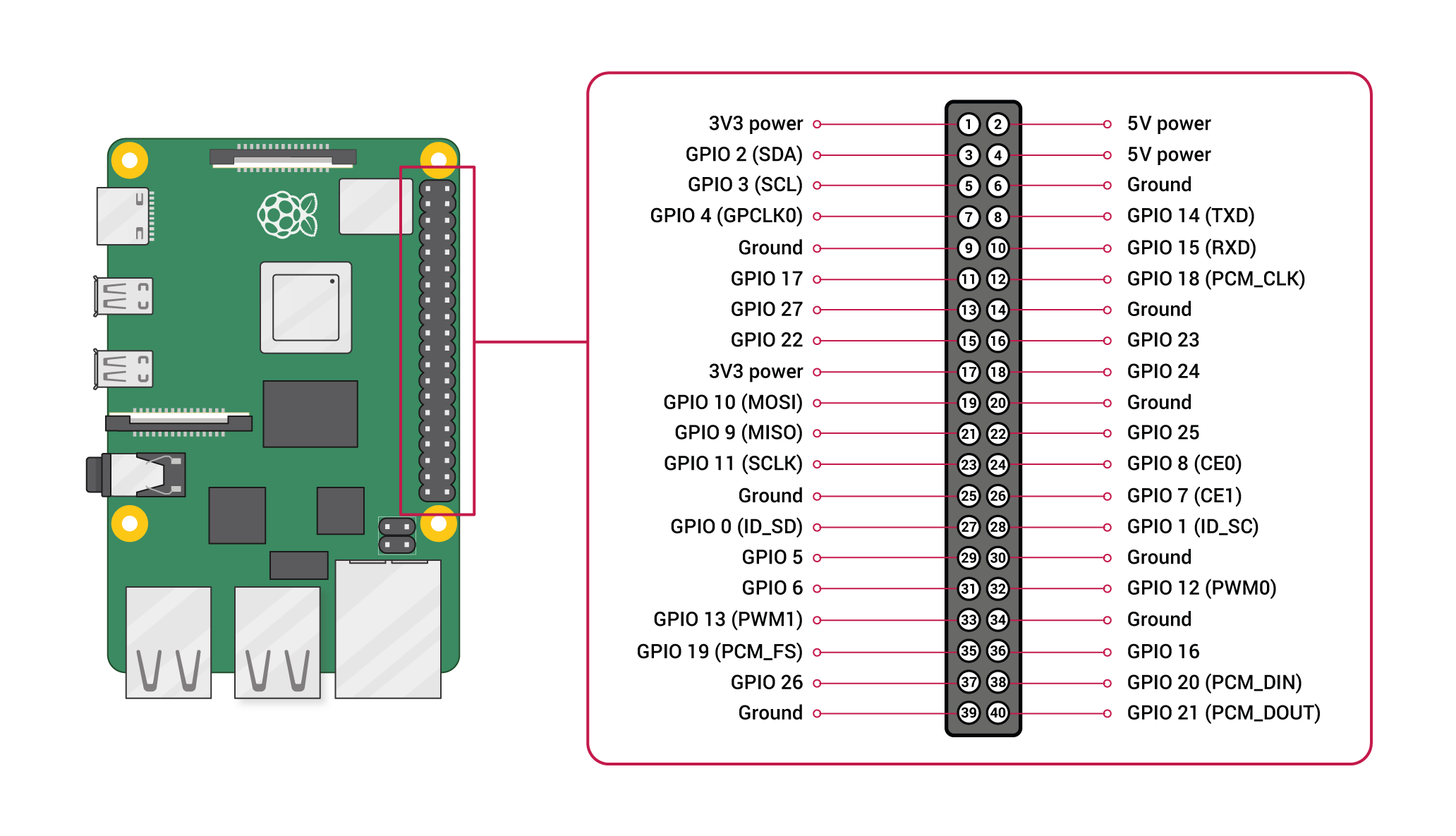
I followed the very helpful instructions here to hook up the ENC28J60 to the RPi4's SPI0 interface.
We won't be connecting the interrupt line for now, so there are just six jumper leads (I've suggested colours) that need connecting:
| Pi pin | Pi GPIO | Jumper colour | ENC28J60 pin |
|---|---|---|---|
| Pin 17 | +3V3 power | Red | VCC |
| Pin 19 | GPIO10/MOSI | Green | SI |
| Pin 20 | GND | Black | GND |
| Pin 21 | GPIO09/MISO | Yellow | SO |
| Pin 23 | GPIO11/SCLK | Blue | SCK |
| Pin 24 | GPIO08/CE0 | Green | CS |
Here's a (not very useful) photo of my RPi4 connected correctly:
The SPI library
Let's start by looking at how we implement SPI communication.
I'm not going to write a long paper on how SPI works and why we need it, because it's very well documented elsewhere. It's recommended background reading, but not essential if all you want to do is get something working.
Look at lib/spi.c. It uses some of existing functions in lib/io.c that you'll remember from earlier tutorials. Specifically, spi_init() sets GPIO 7, 9, 10, and 11 to use the ALT0 function. Cross-referencing with the BCM2711 ARM Peripherals document, page 77, you'll see that this maps SPI0 to the GPIO header. GPIO 8 is mapped as an output pin, since we'll use this to signal to the ENC28J60 that we want to talk. In fact, the spi_chip_select() function takes a true/false (boolean) parameter which either sets or clears this pin.
Looking at the SPI0 register map on page 134, we see this reflected in the REGS_SPI0 structure. This gives us handy access to the SPI0 peripheral's memory map.
Our spi_send_recv() function then sets us up for some communcation:
- Sets the DLEN Register to the number of bytes to transfer (a length we passed into the function)
- Clears the RX & TX FIFOs
- Sets the Transfer Active (TA) flag
Then, whilst there's either data to write or data to read (and we haven't written/read more bytes than we asked for), we write to/read from the FIFO using the buffers we passed in. Once we think we're done, we wait until the SPI interface agrees i.e. the DONE flag in the CS Register is set. If there are extraneous bytes to read, we just throw them away (well, dump them to the screen for now because this shouldn't happen).
Finally, to be absolutely sure, we clear the TA flag.
I've then set up two convenient functions spi_send() and spi_recv() which exercise _spi_send_recv(), mainly to make future code more readable.